ZENITH ZODIAC 650 CONSTRUCTION LOG
The following is my construction log for my Zenith Zodiac 601 / 650. This project was completely scratch built and I used my own CNC router to fabricate many of the airplane parts.
This log details my work from 2007 to 2010 but does not show completion of the airplane. This was left here for reference by other builders, and hopefully it helps others working on similar projects.
Getting ready (Zenith workshop, 16' table, CNC, and flanging dies)Building wing ribs
Metal Brake lessons
Corrosion protection
Metal Brake redesign
Angle Iron Brake Plans
Bending the Main Landing Gear
THIS PROJECT WAS SOLD AND NOT FINISHED
In 2010 my family moved from Illinois to Oregon and it became problematic to move the project. A buyer was found and the Zodiac 650 found a new home.
MARCH 2007
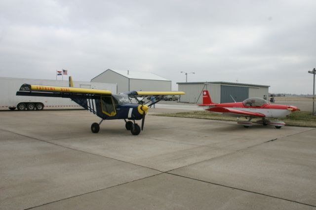
I went to Zenith Aircraft in Mexico, Missouri and took the two day factory workshop. It was a lot of fun and very interesting. However, I was finished with the tail before lunch on the first day...
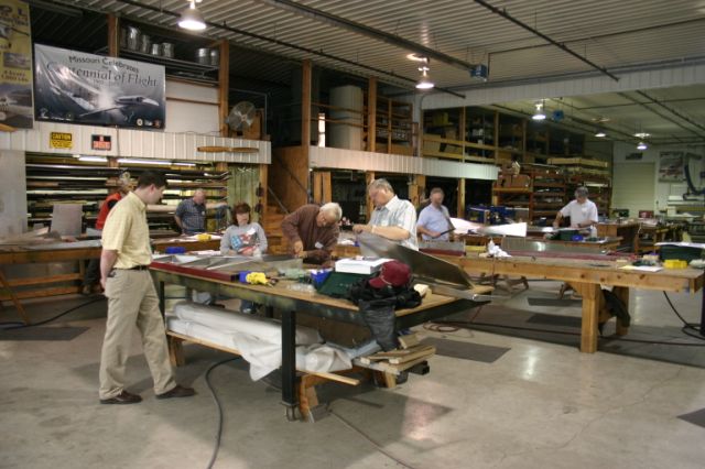
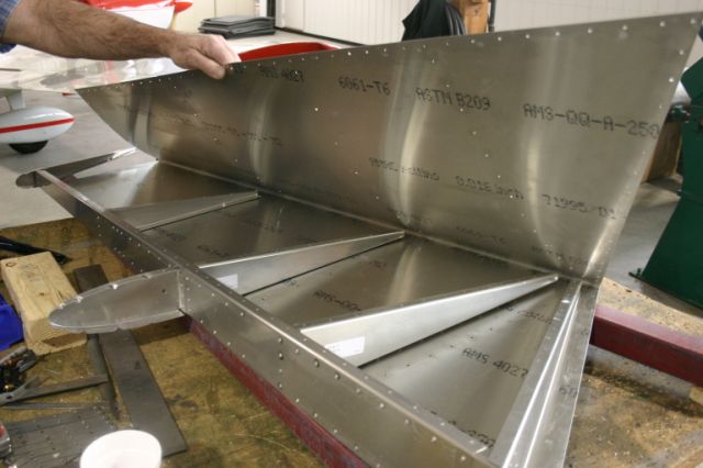
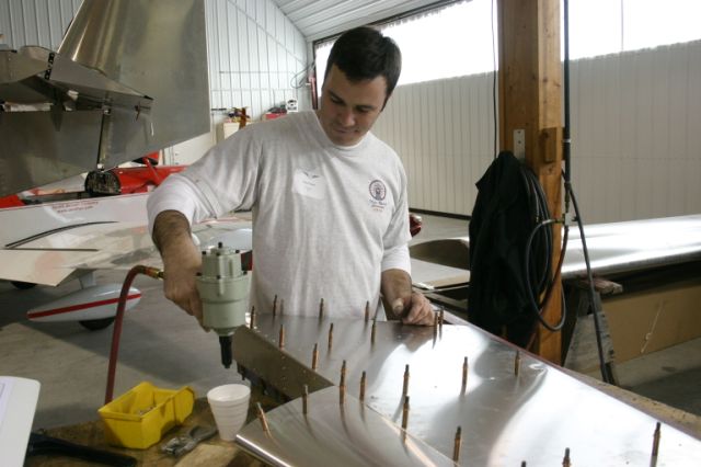
(thanks to some help from my workshop partner)
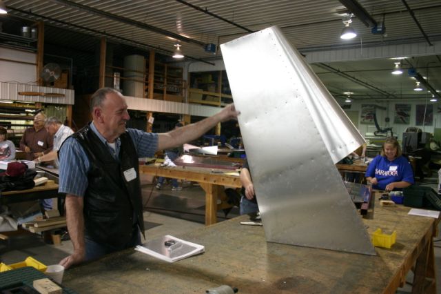
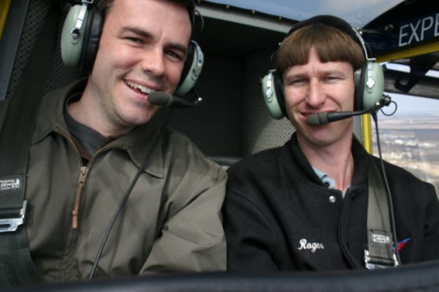
...so I got to use my time to ride along in the factory 601XL.
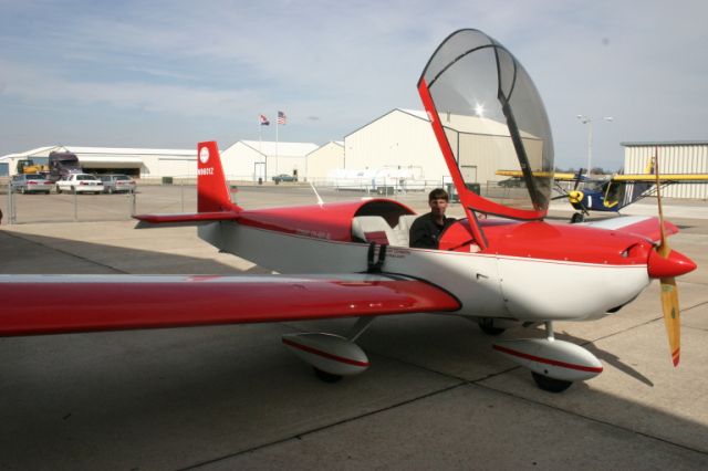
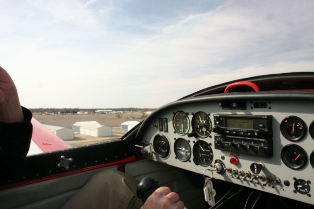


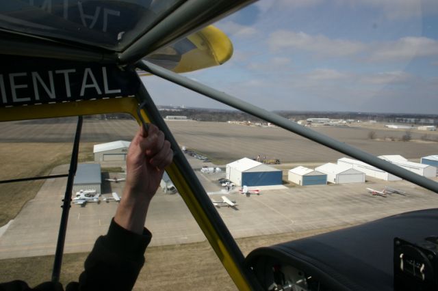
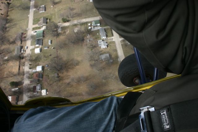
The next day, I rode in the 701. The view is overwhelming, especially down, and I had enough after about ten minutes.
MAY 2007
Using two I-joists, 3/4" plywood, 2x4's and 2x6's, and two sheets of 3/4" particleboard, I built a 4'x16' work table specifically for the 601XL.
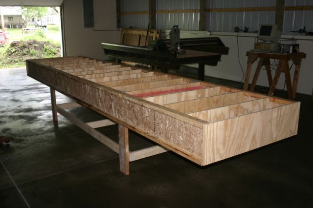
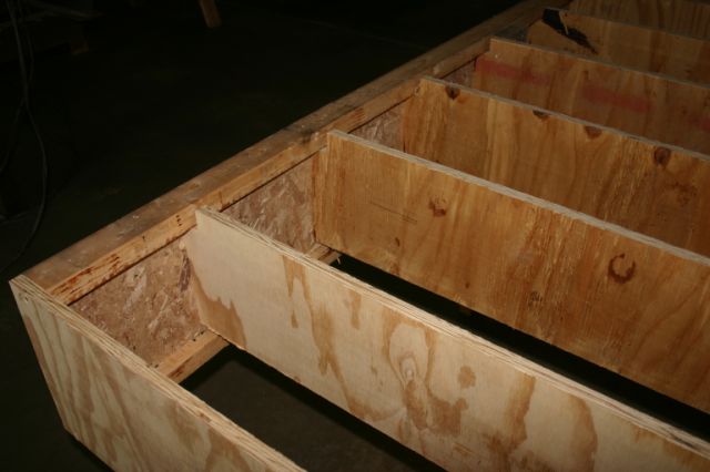
Although shown here clean and in the corner, I relocated this table to the center of the work area and placed a second 8' table next to it. The two tables make an L-shaped work surface with 12' in two directions.

APRIL 2009
Finally getting around to building the airplane!
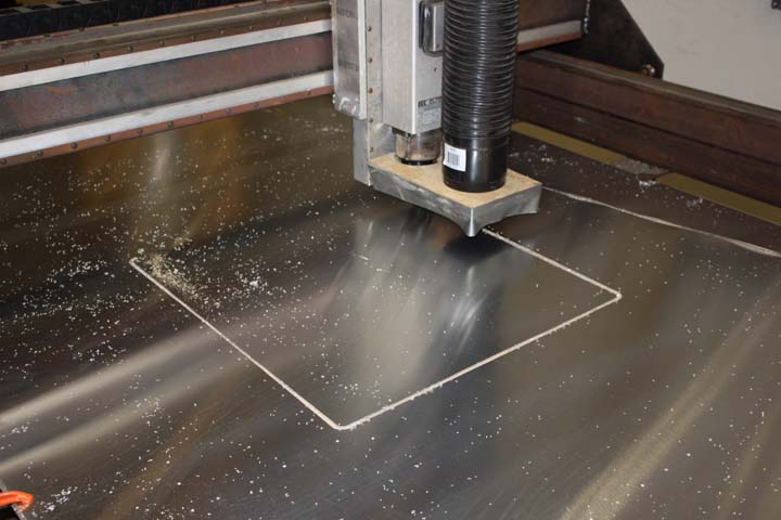
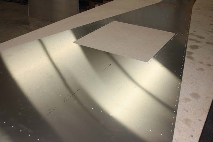
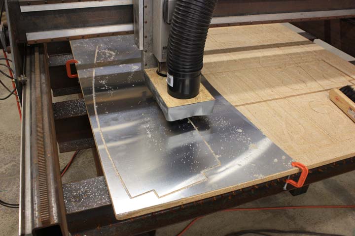
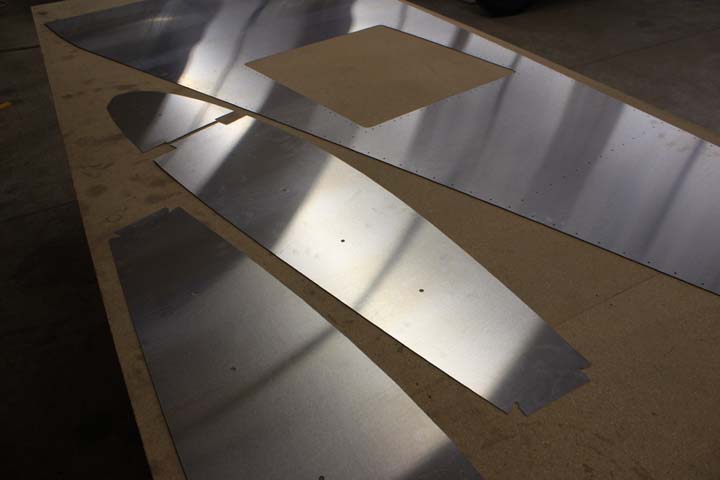
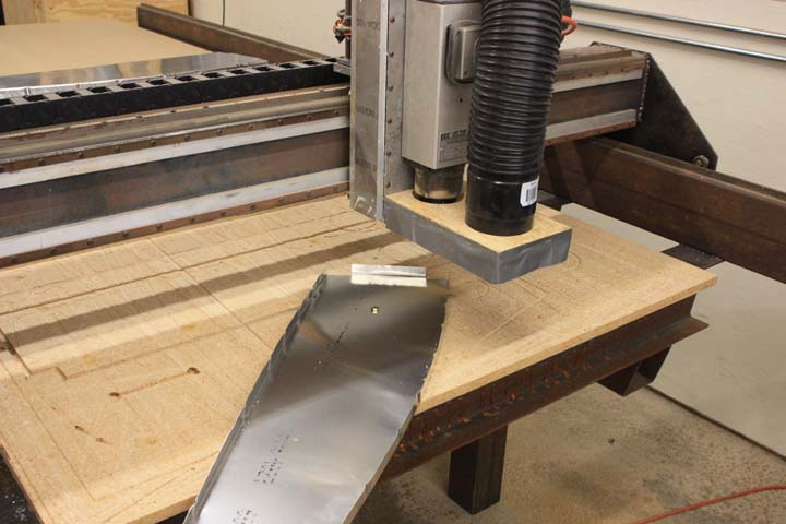
I have a homebuilt CNC that does a great job. It takes just as long to write the CNC file and cut one part as it would to mark up the sheet and cut it by hand. However, it does a much better job at cutting straight clean edges and drilling perfectly spaced holes.
MAY 2009
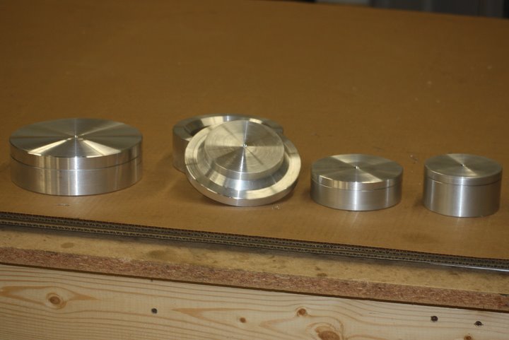
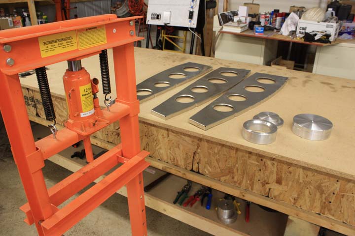
I turned the lightening hole flange dies out of 6061 on my lathe. If I had to guess, I would say I have at least a man-day or two in each one.
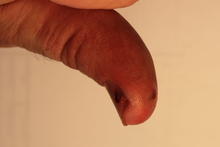
This is what it looks like when you push a broken 5/32" drill bit all the way through your thumb. This happens and is just another cost to consider when thinking about scratch building an airplane. Yes Mom, I'll be more careful.
JUNE 2009
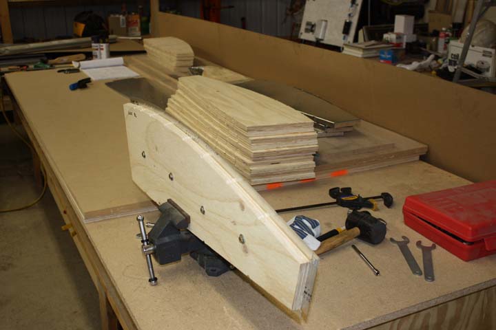
At this point, I have cut out all of my ribs blanks. I cut a few large pieces first, such as the fuselage skins, so I could cut ribs from the scrap. I have also cut all of my rib forms from 3/4" plywood (no aluminum backer was used).
So now I'm all set up for production...
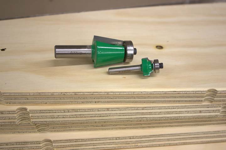
The two bits I used to dress the form blocks is an 1/8" roundover and a 10 degree bowl cutter (the kind you use to pattern rout a kitchen sink in a solid surface countertop). The reliefs for the flange crimps were freehanded with a 1/2" straight cut bit; I just cut in a little until it looked right.
As opposed to a flycutter, I used my CNC. I just routered a hole through the table, bolted down the piece, and wrote a quick routine to cut a 115mm or 95mm circle.
IF I EVER HAD TO DO THIS AGAIN... I would pre-cut the lightening holes and relocate the construction holes closer to the flange edge. I would also cut out the spots where the crimps are so no crimping would be necessary. If I could then just figure out how to press over the flanges, I would be in business!
I initially used a mallet to hammer the dies to flange the holes, but the press works much smoother. At this point, my wrists are killing me from beating over all of those rib flanges.
My Brake is Broke...
So I built a 8' metal brake out of angle iron, a continuous hinge, and bolted it to my 8' table and it's really no good for anything 8' long. I tried to bend the fuselage Z stiffeners, not enough clearance. I tried to bend the 0.040" thick longerons, not strong enough.
So, I took all my metal to my friend's sheet metal shop to use his actual 8' brake. I wrapped the sharp edge of the brake with a 8' piece of scrap, bent it all the way over, and left it in place which gives a nice radius. Unfortunately, the radius was a little smaller than 1/8". I then adjusted the brake back to account for the wrap and tried to bend the longeron. Yep, same outcome as with my brake... inaccurate and curved!
So I tried his 8' long 60 ton press brake and that worked nicely, except that his edge radius is 1/16".
Left with either a 1/8" radius but curved bend from my brake, an undersized radius and curved bend from his brake, or a straight but 1/16" bend from his press brake, I said to HELL with it... and bought some 3/4" x 3/4" x 1/16" angle for the longeron.
And that worked nicely.
[ I did work out a method that uses my angle iron brake... see a few pictures below. ]
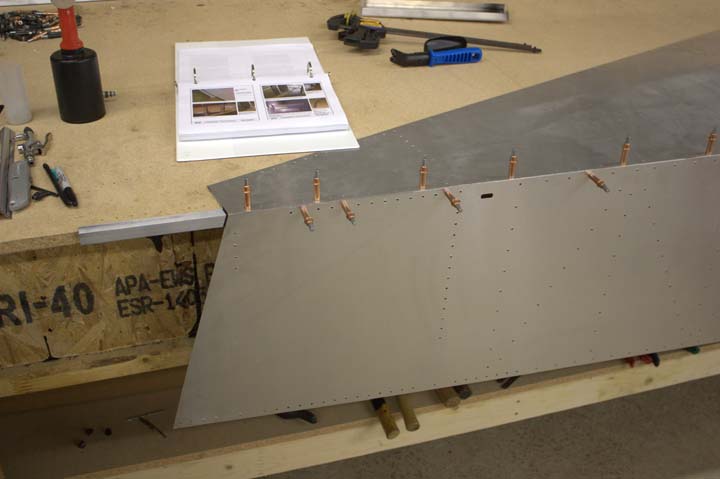
The two formers at the back of the fuselage will have to be decreased in width a touch to account for the fact that I'm running the sides flush with each other all the way down, but that's not too much of a big deal.
Also, the 3/4" x 3/4" x 3/32" angle used for the front longeron is an unusual item, much like the 1/16" thick stuff, so I just used 1/8". Substituting thicker material for the front and rear longerons will add a 2.8 pounds total.
JULY 2009
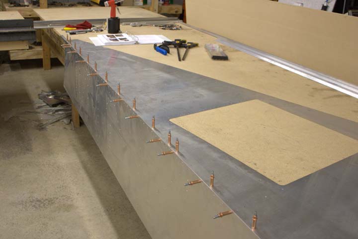
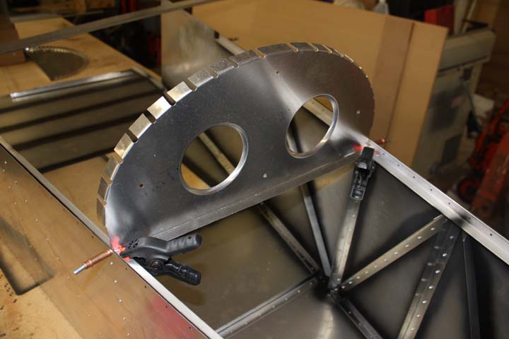
There's a lot going on in the picture below. First, you'll notice I built this former using a different method: I tabbed the flanges and predrilled the lightening holes on the router. This worked much better since it took less time to make the part.
Second, you may notice that I am putting on corrosion protection between the assembled parts. It seems that there are two sides on the internet on what to do: either do nothing or use the most extreme protection possible, such as zinc-chromate primer or an automotive urethane primer with top coat (both are really hazardous). My simple solution is to use Rustoleum primer and Rustoleum gloss enamel, easily found in rattle-cans from Walmart. I apply the paint the night before allowing enough time for the paint to dry and then rivet the parts the following day.
And although you can't see it in the picture, this is the THIRD TIME I built this part. This part, like a few others, don't exactly fit. Apparently, the new 650 is full of modified 601 parts and not all the minor changes have been ironed out in the current plans (my plans are dated 08/2008). At this point, I'm simply using the plans as a guide and redrawing whole assemblies making sure the parts all fit together on CAD first. Since I'm using a CNC router to cut the parts, I have to draw the parts anyway, but at least in this fashion I can iron out any problems prior to cutting material.
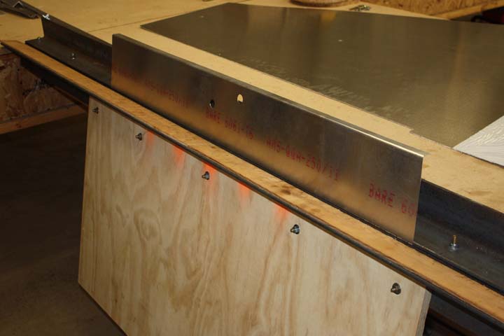
In making the 0.040" thick parts for the fuselage, I think I may have a method to make the small angles without ending up with a curved piece: If you plan to make a batch of angles, such as 6B2-1 (rear longerons) or 6T1-L (standard angle), cut out some material that is the correct length, but not cut into strips; leave it wide. The wide piece bends without the warp, then you can cut the angle off the end and bend the wide piece again.
The brake still isn't strong enough to bend 8' long pieces well, but I'm getting by.
BRAKE REDESIGN
I got to the point of the fuselage where I needed to bend 1/4" radius material for the firewall parts. This means I need to build a new brake or modify the one I have. Unhappy with my first and second build of my current bending brake, I just tore my brake apart and started from scratch, again. And, I finally sat down at the computer and worked out all the details, which is something I should have done in the first place.
This is the detailed result:
Angle Iron Brake Plans
FEBRUARY 2010
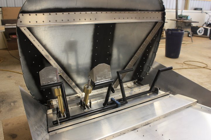
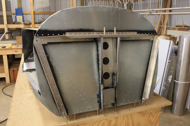
JUNE 2010
SCRATCH BUILDING LANDING GEAR
This part of the project is so far my least favorite. The plans indicate to cold bend with a 3" radius... and that's about it. Hmmmm, bend a 3/4" x 7" plate of 6061-T6 around something that's 6" in diameter; that should be easy enough. YEA RIGHT.
I started with the flat stock and used my CNC to router it down to size. I could have simply used a hand router and a pattern, but I had the CNC. I used a small carbide tipped bit, use cutting fluid, and took several passes. Once that was cut out, I rounded over the edges with a hand router. I used a carbide tipped roundover bit with a bearing and used cutting fluid. The cutting fluid really helps keep the cut clean and any number of oils would work sufficiently (WD-40, 3-in-1 oil, vegetable oil, motor oil, etc.), just don't cut it dry. Sorry I didn't take any pictures of this process but you get the idea.
There aren't a lot of options when it comes to finding something to bend the gear around. It has to be massively strong. I used a section of heavy wall 6" pipe, the wall sides were about 1/2" thick and the actual diameter was 6-1/2".
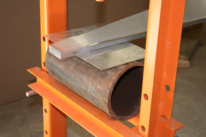
For the small ends of the gear, I built a simple jig out of some 3" schedule-40 steep pipe and some scrap steel. The two pipes are spaced 10" on centers and welded to the steel. If they were any farther apart, they would be wider than the short end of the gear.
[In hindsight, it would have been a lot easier if I did not cut the gear to length and had left the several inches of aluminum hanging off the tips. Then I could have used the same jig for these little ends that I used for the two middle bends.]
In all cases, I put a piece of scrap aluminum sheet between the steel and the landing gear to protect against scratches.
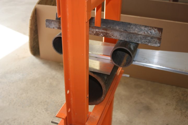
Notice the 4' cheater pipe used to pump the press. The extra leverage is needed, but more importantly it allowed me to operate the press from a safer distance.
[And speaking of safety, I should have replaced the steel that holds up the jack first... that vertical 1" bar that is welded on to that steel slid sideways, bent, and then failed suddenly and violently! Notice the difference between this picture and the last pictures... that piece has been replaced.]
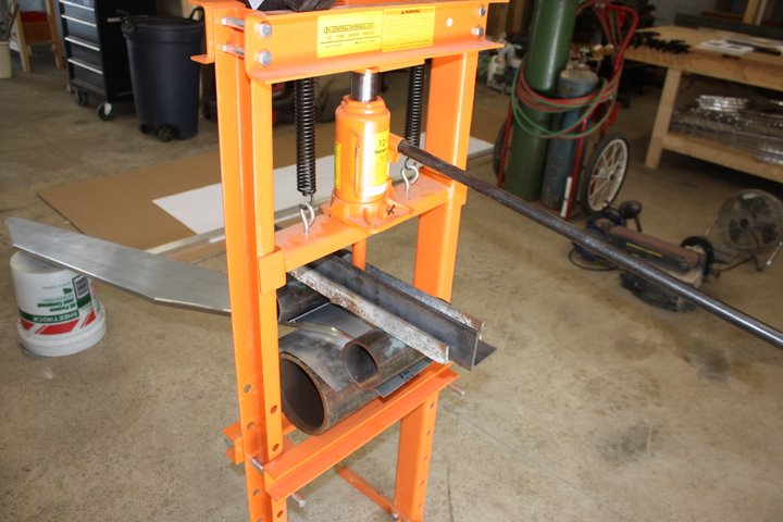
I then used a digital level to measure the angle of both sides, the sum of the two measurements equals the total bend.
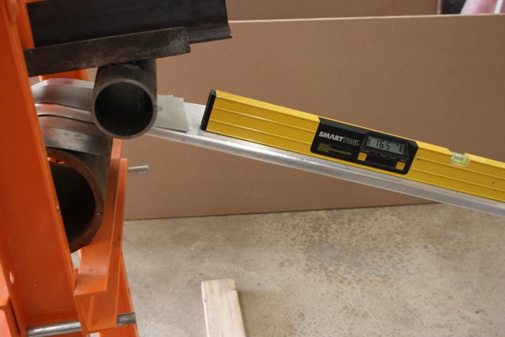
On the short ends of the gear, the spring back was 8 degrees. In other words, to get a 46 degree bend, I needed to bend it to 54 degrees and it sprung back to 46 when I took it out of the press.
I Initially tried to use the same jig for the bends across the wider part of the gear. The jig smashed flat. As shown below, I used two more pieces of 3" pipe welded between two strips of 3/8" steel plate. The two pipes were spaced further apart, something like 16" between centers. This extra distance allows additional leverage making it a bit easier on the small pipes (the big pipe still sees the same forces).
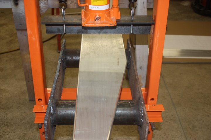
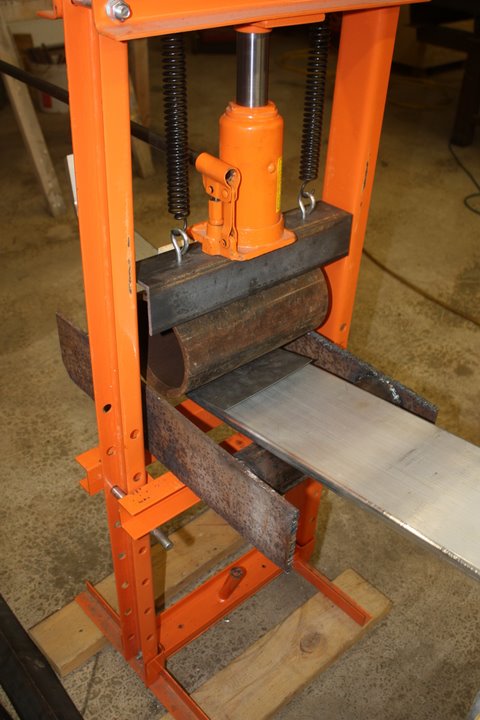
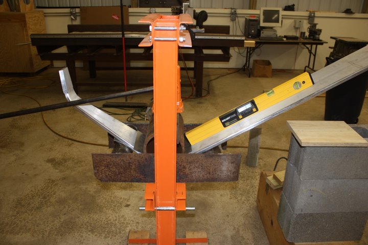
The springback on the wider bends was 10 degrees.
Most of my time was measuring and getting things square. GETTING EVERYTHING SQUARE IS REALLY IMPORTANT. I squared the big pipe to the gear, the gear to the jig, the jig to the press, and even the press to the building. Everything was square; this way, if something was out of square, I would more easily notice it. I squared everything before I put any pressure on the press. I squared everything after putting a little pressure on. I even check several times during the process. The last thing I wanted was gear that would drive me sideways down the runway! And guess what, my gear came out without any weird twists!
I was able to get the wide bends within 1/2 a degree of each other kept the bend centers pretty close to my mark (40mm from the point where the taper begins). All in all, the installed height between the left and the right side is within 3/8".
IF I HAD TO DO IT AGAIN, I would leave the short end of the gear with a few inches of additional material and space the pipes out a bit. This extra material would then get cut off once the whole gear is bent allowing both sides to be exactly the same height.
THAT'S ALL... THIS PROJECT WAS NEVER FINISHED
When we from Illinois to Oregon, the project was sold. I wish the new owner the best of luck!